Hadron Tutorial
Please make sure that you have studied the "Introductory Tutorialö, before you visit this one!
This hadron tutorial is intended to make you familiar with the structural concepts and graphic conventions of IPPÆs drawings of mesons and baryons, so you can get the most out of them.
1) How IPPÆs Graphic Convention For A Defect-Pair Is Derived
- A: C-void planes with a solidly filled interior
- B: C-void planes connected by a column of ECEs
- C: C-void planes connected by a column of lattice cube
- D: Final representation
2) Picturing Defect-Pairs Dynamically - The Collapse And Uncollapse Of Their C-voids
Defect-pairs form only in regions in which the lattice is fully collapsed. Defect-pairs form only in regions of space in which there is enough capturable shrinkage to fully collapse the lattice. Therefore, a hadronÆs hovering lattice-density oscillation must have sufficient mass-energy to saturate its central region during the peak density phase of its cycle. This requirement accounts for the very brief moments when a defect-pairÆs c-voids are fully uncollapsed, as shown below.
3) Defect-Pair Spacings
A defect-pair's spacing is the distance in lattice units between the centers of its c-voids. These spacings vary between 5³ to 15³, usually increasing with the number of defect-pairs clustered at the hadronÆs center. Charged defect-pairs (those having odd spacings) are distinguished by a single girder color (gold for + +, blue for - -). Neutral defect-pairs (those having even spacings) have both girder colors, which meet at the middle of the defect-pair. Below are four defect-pairs: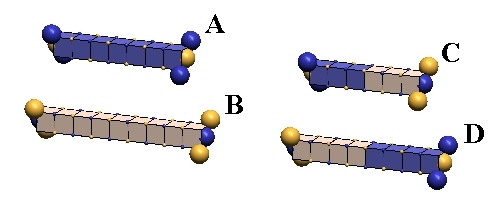
ōAö and ōBö are charged defect-pairs, spaced 7³ and 9³. ōCö and ōDö are neutral defect-pairs, spaced at 6³ and 8³. (³ = one lattice unit).
4) Defect-Pair Mass-Energies
A compelling feature of IPPÆs defect-pairs is that their individual mass-energies vs. their spacings can be accurately calculated, and that these values hold precisely throughout the whole spectrum of hadron particles. Here are the equations for calculating these mass-energy values, in MeV, and graphs and tables showing the results of these calculations:| Odd defect-pair spacing mass-energy (MeV) = |  |
| Even defect-pair spacing mass-energy (MeV) = |  |
5) Defect-Pair Slant
C-void defects can pair only when their zones of expansion & contraction are mutually canceling (i.e., orthogonal), and when their centers are in cardinal lattice directions from each other. If we call the direction of expansion of the two c-voids their ōslantö, we see immediately that there are two equally probable ōslantö directions that permit c-void pairing. We show these two forms, below, which we will distinguish by calling the left figure, ōL-slantö, and the right one, ōR-slantö.
6) Slant Forms of Two-Defect-Pair Clusters
Orthogonal defect-pairs have two possible slant configurations. Below, left, we show a two-defect-pair cluster with an x-axis L-slant defect-pair, and a z-axis R-slant defect-pair. We refer to this mixed slant arrangement of orthogonal defect-pairs as A-slant (for alternate slants). Below this is the other A-slant possibility (X=R, Z=L). Below, right is a two-defect-pair cluster where both x-axis and z-axis defect-pairs have L-slant. Below this is the other S-slant possibility (X=R, Z=R). We refer to this slant arrangement of orthogonal defect-pairs as S-slant (for same slant}. It should be obvious that S-slant neutral kaons have equal probability of being created in either R-slant or L-slant configurations, and that A-slant neutral kaons have equal probability of having L-slant or R-slant x-axis defect-pairs.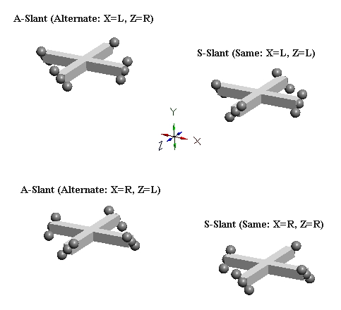
7) Slant Forms of Three-Defect-Pair Clusters
The slant forms of clusters of three mutually orthogonal defect-pairs (e.g., nucleons) can obviously occur in eight configurations (2x2x2). However, it is useful to think of these as just two basic types, T-slant & M-slant. The two possible T-slant forms are shown below, left, and two of the six possible M-slant forms is shown below, right. The planar slant relationships for the three two-defect-pair subgroups in each form are shown as equal to A or S. A refers to A-slant and S refers to S-slant. The T-slant form gets its name from the tetrahedron produced by the projection of the axes of expansion of its six c-voids. The M-slant form, or mixed form, gets its name from being produced merely by altering the slant of one of the defect-pairs (in the case below, the Y defect-pair) of either of the two T-slant forms. IPP is able to prove (see page 3-25 of online book) that all nucleons (protons, neutrons, and antiprotons) exist only the two T-slant forms. M-slant forms are apparently unstable, and occur only in certain kaon resonances.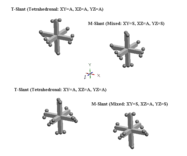
8) Defect-Pair Bonding - IPP's Concept Of The Strong Force
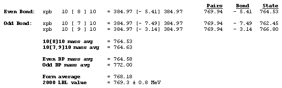
Since the c-voids of defect-pairs are spaced apart, the mutual cancellation of their orthogonal zones of expansion & contraction distortion is incomplete! Hence, there will be residual expansion/contraction distortion extending from each end of defect-pairs. Thus, when adjacent defect-pairs approach each other along a common pairing axis, with their adjacent slants crossed (of opposite orientation), further cancellation of distortion (mass-energy) can occur. This cancellation of mass-energy binds the two defect-pairs together, and is termed a ōparaxial strong-force bondö, or, more usually, a ōparaxial bondö. Another possibility of distortion cancellation occurs when the two defect-pairs lie parallel to each other, with their respective c-voids lying in the same cardinal plane and in lattice face-diagonal direction from each other. Cancellations of mass-energy in this configuration are termed, ōdiagonal strong-force bondsö, or, more usually, a ōdiagonal bondö. We show examples of these two types of bonds, below:An Example Of A Paraxial Bond - rho(770):
The rho(770) is the simplest example of a paraxial bond. In the upper example, the green girder of 8³ length is the symbol for a paraxial bond between two 10³ defect-pairs whose adjacent c-void defects are "crossed", and opposite in polarity. In the lower example, where the bonded c-voids have the same polarity, the bond spacing will clearly be odd. Charged rhos also form, where one of the defect-pairs is charged, one neutral; and neutral rhos form, where the two bonded defect-pairs have opposite charge. Double charge rhos evidently do not form, probably because there is too much repulsion to permit the bond to form. Paraxial bond spacings tend to scale inversely with the size of the bonded defect-pairs. This will become clear as you study the numerous examples of meson and baryon resonances in our animated drawings.
An Example Of A Diagonal Bond - eta(547):
The eta(547) is the simplest example of a diagonal bond. In states 1 and 3, two neutral 8³ defect-pairs of opposite slant site parallel to each other, such that their respective c-void defects lie in face-diagonal directions from each other at spacing of 5³/ (five face-diagonal lattice units, or 5v2). In states 2 and 4, opposite-charge 9³ defect-pairs site in the same geometry at the same spacing of 5³/. The eta(547) alternates, by charge-exchanges, between these two forms as it translates through the lattice. It is characteristic of diagonal bonds that the bonded c-void defects have opposite polarity, and that they occur dominantly in neutral resonances. With further study, you will understand why.
An Example Of Ring Diagonal Bonds - eta'(958):
The eta'(958) is the simplest example of ring diagonal bonds. Ring diagonal bonds consist of four parallel defect-pairs sited equidistant from each other in face-diagonal directions, with their "slants" alternating around the ring, as shown. The eta'(958) closely resembles the eta(549), having 8³ defect-pairs spaced 5³/ apart. It differs only in not altering its defect-pair spacings to 9³ as it translates through the lattice. Defect-pairs in a ring arrangement develop four diagonal bonds. However, IPP defines a ring-diagonal bond as just two of these four bonds in its bond mass deficit calculations, because in some particles only half a ring bond is formed. Ring diagonal bonds are found in most meson resonances of higher mass-energy, and in all nuclei except the deuteron.
An Example Of Multiple Bond Types - alpha particle:
Most particles possessing ring-bonded defect-pairs also have paraxial-bonded defect-pairs. The two protons and two neutrons comprising the alpha particle are interconnected with both types of bonds, as shown below.
9) Calculating Bond Mass-Deficits (in MeV)
Calculating the mass-deficits of strong force bonds between defect-pairs is straightforward in IPP, because all the bond elements (defect-pair spacings & bond spacings) are quantized. Here are the relevant equations in succinct form. To learn how these are derived, see Chapter 2 of the online textbook.Paraxial Bond Equation:
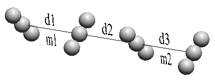
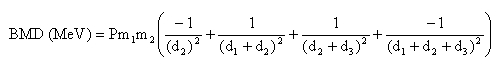
m1 and m2 are in MeV; d1, d2, d3 are in lattice units; P = 1 / 294.17
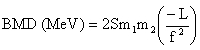
Diagonal Bond Equation:
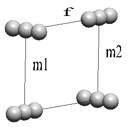
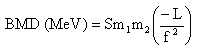
m1 and m2 are in MeV; f is in face-diagonal lattice units; S = 1 / 511.92
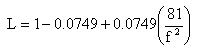
Ring Diagonal:
10) Defect-Pair Cluster Charge-Exchanging
What Is A Charge-Exchange?
IPP views a hadron charge-exchange as the process by which opposite-polarity c-voids sited in face-diagonal directions from each other can move into each other's (approximate) locations. Charge exchanges can take place only during the "void" state of a c-void's hovering oscillation cycle, which, you will recall, is during the phase when the surrounding ECEs have their lowest packing density. IPP calls this (lowest packing state) "the central rarefaction phase" of the hovering oscillator's lattice density oscillation.